Model Train
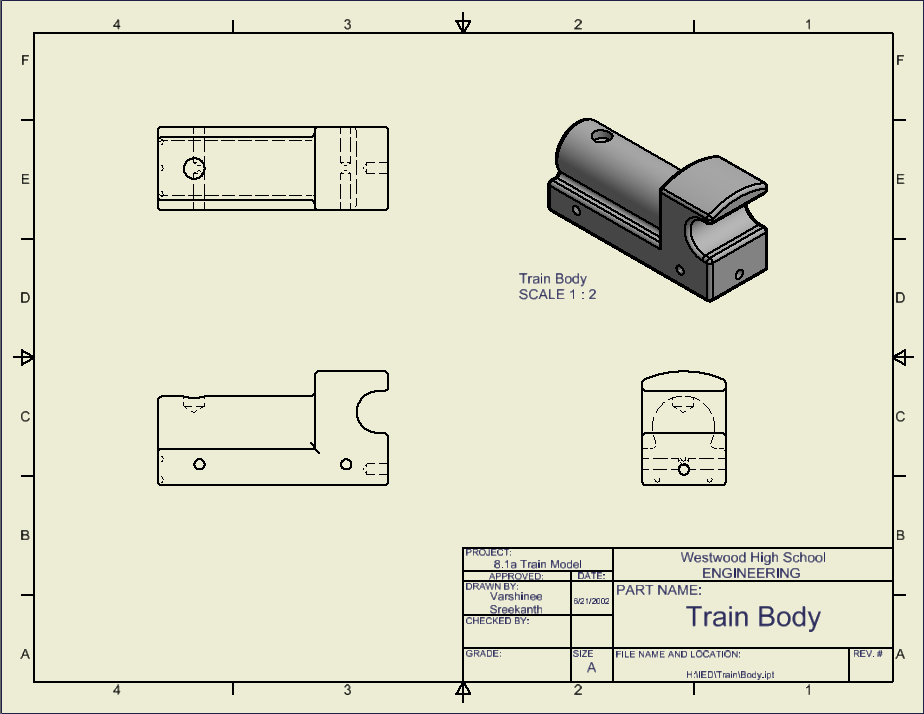
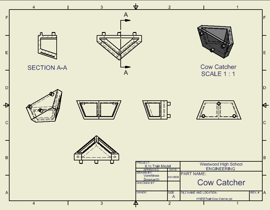
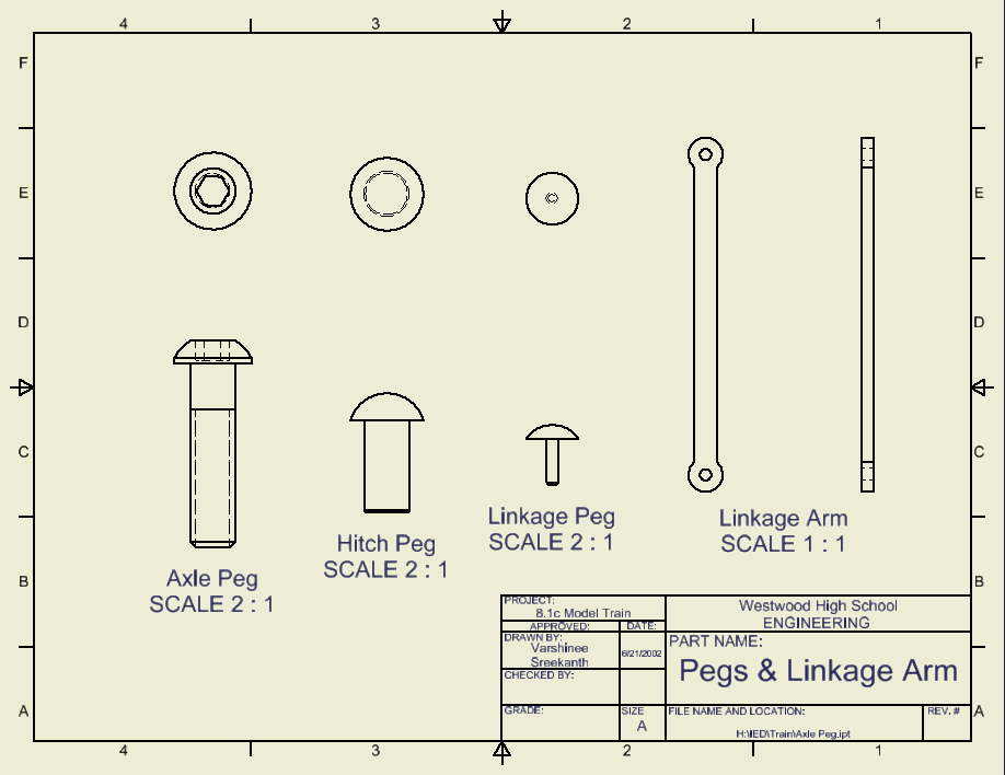
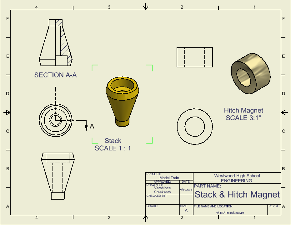
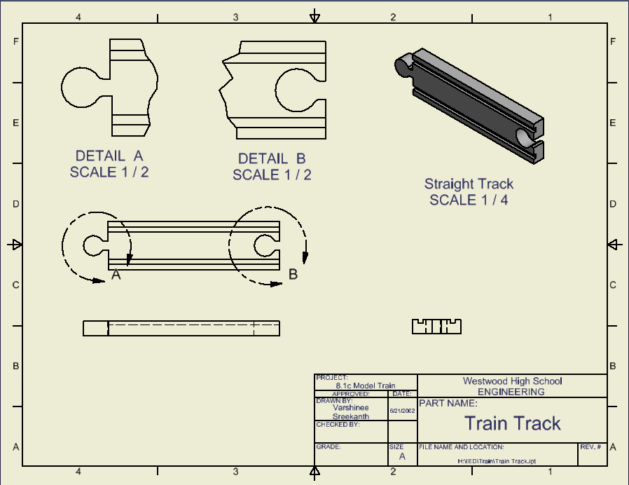
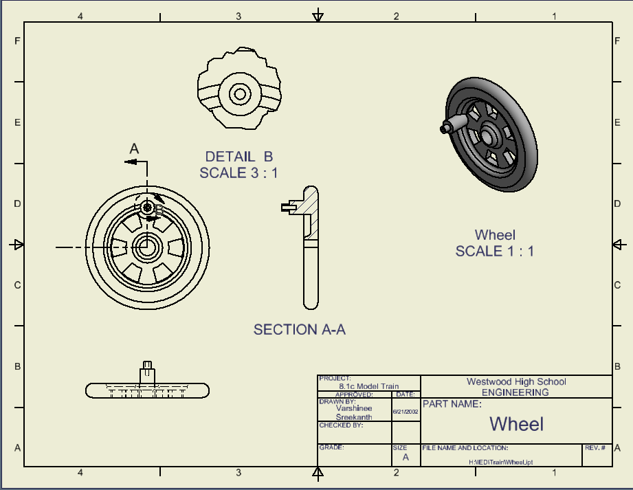
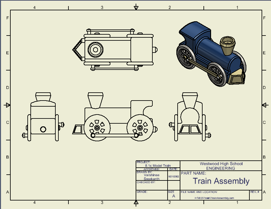
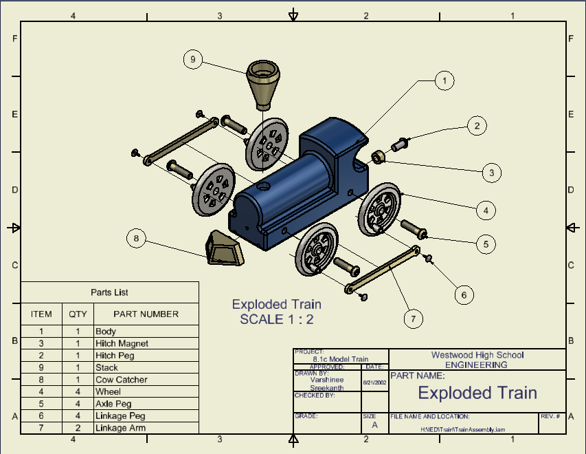
In Inventor, we have been working on a model train. Carefully following directions, we recreated individual parts of a train and assembled it together. The parts of the train included the body, stack, track, wheels, and various pegs and screws. the final result was a 6-inch-long fully-functioning model train. I represented all these using engineering drawings, and also made a drawing for the exploded view, to fully illustrate the different parts of the train and how they fit with the rest.
Engineering Drawings
Conclusion Questions
1. The drawings are composed of different line conventions to more easily convey the 3D figure. Section lines, object lines, etc. show us how the object is shaped, cut, or something else.
2. A sectional view shows the inside of a figure to fully convey to the audience what the object is. When an object looks different on the inside, a section view helps show that.
3. An auxiliary view shows an angled face flat-on, so that we may more effectively and accurately dimension that angled face.
4. Symbols are used in place of words to identify hole types to minimize clutter and make the engineering drawing easier to read.
5. Using algebraic equations instead of numerical values to define dimensions allows us to easily scale dimensions, because if we change one dimension, the rest will change as well.
6. Constraints that can be applied to CAD sketches or models are perpendicular lines/planes, concentric circles, and horizontal or vertical constraints.
7. CAD drawings can be easily changed, can represent 3D figures more effectively, and allows for computers to do some actions such as calculating and scaling instead of humans, as computers can do some things faster and more accurately than humans.
